THE 700 W THERMAL CHALLENGE
The NVIDIA H100 SXM has a 700 W thermal design power, B200 reaches 1,000 W, and next-generation GPU platforms are expected at 1,200-1,500 W per GPU. At 8 GPUs per node, a single server generates 5.6-8 kW of heat from GPU silicon alone, plus CPU, memory, networking, and PSU losses pushing node-level dissipation to 7-12 kW. In a 12 kW per-node scenario with 12 nodes per rack, each rack produces 144 kW of heat. Removing 144 kW from a single rack using air requires moving roughly 30,000 CFM of air - equivalent to a 20-foot-diameter fan duct and a raised floor depth that is mechanically impractical.
The thermal density curve tells a stark story. Traditional data centers operate at 5-15 kW per rack with PUE of 1.3-1.6 using air cooling. At 30-40 kW per rack, chilled water rear-door heat exchangers or in-row cooling units can still manage the load. Above 50 kW per rack, which is the base case for GPU clusters, air cooling becomes thermodynamically insufficient regardless of fan speed or floor tile configuration. The air volume required exceeds the physical cross-section of the rack, and the temperature rise across the rack creates hotspots that violate GPU inlet temperature specifications of 20-30 degrees C per ASHRAE A2 guidelines.
AIR COOLING AT HIGH DENSITY
Before reaching the density wall, air cooling can be pushed to 35-40 kW per rack with careful engineering. The approach uses hot-aisle containment (HAC) or cold-aisle containment (CAC) with chilled water computer room air handlers (CRAH) or direct-expansion (DX) computer room air conditioners (CRAC). Rear-door heat exchangers (RDHx) mounted on each rack can boost air cooling capacity to 50 kW per rack by capturing exhaust heat directly at the rack outlet. The RDHx removes 60-70 percent of the heat before it enters the room air, reducing the total airside demand by a corresponding factor.
The operational cost of air cooling at high density is driven by fan power. At 35 kW per rack, the cooling infrastructure fan power alone accounts for 8-12 percent of total IT load - a PUE penalty of 0.08-0.12 - versus 3-5 percent at 10 kW per rack. Air-side economization (free cooling) using outside air can reduce mechanical cooling hours from 8,760 to 2,000-4,000 depending on climate, saving $0.5-1.5 million annually per 10 MW of IT load. However, direct air economization introduces particulate and humidity control challenges that are amplified in GPU clusters due to the tight environmental tolerances of NVMe SSDs, optical transceivers, and high-density connectors.
| Cooling Method | Max kW per Rack | PUE Range |
|---|---|---|
| Raised Floor + CRAH | 15-20 kW | 1.3-1.6 |
| Hot/Cold Aisle Containment | 20-35 kW | 1.2-1.4 |
| Rear-Door Heat Exchanger | 35-50 kW | 1.15-1.3 |
| Direct-to-Chip Liquid | 60-150 kW | 1.05-1.15 |
| Immersion (Single-Phase) | 40-80 kW | 1.02-1.08 |
| Immersion (Two-Phase) | 80-200 kW | 1.02-1.05 |
DIRECT-TO-CHIP LIQUID COOLING
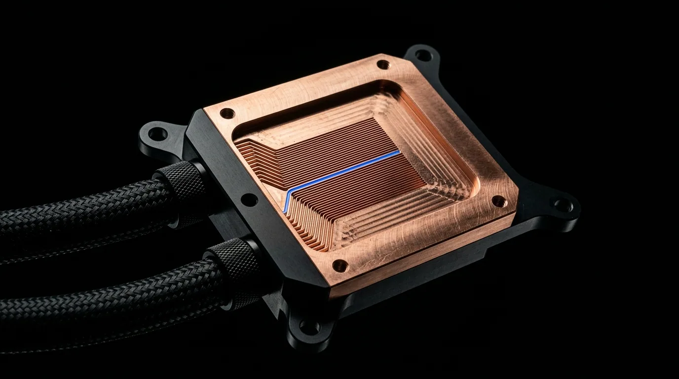
Direct-to-chip (DTC) liquid cooling is the dominant architecture for GPU clusters today, deployed at scale by CoreWeave, Microsoft, and Meta for their H100 and B200 fleets. A cold plate mounts directly to each GPU and CPU package, circulating a dielectric fluid or treated water-glycol mixture at 20-40 L/min per server, with inlet temperatures of 18-25 degrees C and outlet temperatures of 40-55 degrees C. The cooling distribution unit (CDU) sits outside the compute row, managing fluid quality (conductivity target below 0.5 microsiemens/cm for dielectric fluids), flow rate, and heat rejection to the building chilled water loop or dry coolers.
The capital cost for DTC liquid cooling has dropped significantly as the ecosystem matured. Installed cost now ranges from $1,500-3,000 per kW of IT load, down from $5,000-8,000 per kW in 2020. This includes cold plates, manifolds, hose management, CDUs, and facility piping. A 10 MW GPU hall requires 2-4 CDUs at 2.5-5 MW thermal capacity each, costing $400,000-800,000 per CDU. DTC liquid cooling enables GPU clusters to operate at 60-150 kW per rack while achieving PUE of 1.05-1.15, compared to 1.3-1.6 for air cooling at equivalent density - a PUE improvement that saves $2-5 million per year in electricity cost for a 50 MW facility at $0.08/kWh.
IMMERSION COOLING APPROACHES
Single-phase immersion cooling submerges entire GPU servers in a dielectric fluid (typically a synthetic hydrocarbon or fluorocarbon) that remains in liquid phase throughout the operating temperature range. The fluid circulates from the tank through a heat exchanger by natural convection or pumped flow. Server modifications are minimal: hard disk drives must be removed, thermal interface materials must be immersion-compatible, and PCIe risers need orientation adjustments for buoyancy-driven flow. Single-phase immersion has been deployed at modest GPU scale by several AI startups, primarily for thermal validation rather than production compute - the operational friction of server extraction, fluid handling, and optical cable management remains high.
Two-phase immersion cooling, using engineered fluids with boiling points of 40-60 degrees C (e.g., 3M Novec 7100, 7200), enables an order of magnitude higher heat transfer coefficient via nucleate boiling. The fluid boils at the hot surface, bubbles rise and condense on immersed coils or a condenser lid, and the condensate returns to the tank. Two-phase immersion can handle 200+ kW per rack with a PUE of 1.02-1.05, making it the highest-density cooling architecture available. However, the engineered fluids cost $200-300 per liter, a 10,000-liter tank fill costs $2-3 million, and annual evaporation losses of 2-5 percent add $50,000-150,000 per year in fluid replacement. These economics have limited two-phase immersion to fewer than 20 production GPU deployments worldwide as of early 2026.
CDU AND FACILITY INTEGRATION
The cooling distribution unit is the critical integration point between the compute row and the facility heat rejection system. A typical CDU for GPU liquid cooling contains: a plate-frame heat exchanger isolating the facility water loop from the IT water loop, variable-speed pumps (2N configuration) sized at 200-500 GPM per CDU, a reservoir and expansion tank, dual filtration with 50-micron and 5-micron filters, and a PLC-based control system managing temperature, flow, pressure, and conductivity. The CDU maintains a pressure differential of 30-50 PSI between supply and return, with per-server flow control via manual or electronic balancing valves.
Heat rejection at the facility level uses either cooling towers (wet or adiabatic), dry coolers, or a heat recovery loop. For a 50 MW GPU cluster, the heat rejection system typically uses 6-8 induced-draft cooling towers with 10-15 MW capacity each, consuming 5-8 gpm per ton of evaporation makeup water. Dry cooler alternatives eliminate water consumption at the cost of 1.5-3x higher fan power and reduced efficiency in hot climates. Heat recovery to district heating or adjacent facilities can recover 20-40 percent of the waste heat value, but the low-grade temperature (40-55 degrees C from DTC loops) limits economic recovery options. A 50 MW GPU data center operating at PUE 1.1 rejects roughly 55 MW of heat to the environment - enough to heat 18,000 typical homes.
COOLING TCO COMPARISON
The total cost of ownership for GPU data center cooling must account for capital investment, operating energy, maintenance labor, water consumption, and the opportunity cost of lost compute density. Air cooling at 20 kW per rack requires the most white space per MW (50-60 racks per MW), driving higher building shell cost, longer cable runs, and increased labor for operations. Direct-to-chip liquid cooling reduces space per MW by 60-70 percent and cuts cooling energy by 40-60 percent. Immersion cooling eliminates fan energy entirely but introduces fluid replacement and server handling costs that are difficult to estimate at scale due to limited deployment data.
The industry consensus has converged to a hybrid approach: air cooling for storage and networking racks at 10-20 kW per rack, and direct-to-chip liquid cooling for GPU compute racks at 60-150 kW per rack. Immersion cooling remains a niche for specific use cases (high-TDP accelerator validation, confidential computing requiring physical isolation, or hyperscale deployments where 200 kW per rack drives land-use economics). The next frontier is two-phase direct-to-chip with dielectric fluid circulation, which combines the density of two-phase heat transfer with the serviceability of cold plates - several CDU manufacturers have announced products targeting this architecture for 2027 GPU generations at 1,500 W+ TDP.
| Cost Factor | Air Cooling | Direct-to-Chip Liquid |
|---|---|---|
| Capital Cost per IT kW | $800-1,500 | $1,500-3,000 |
| Cooling Energy (% of IT load) | 10-20% | 3-8% |
| Max Rack Density | 35-50 kW (with RDHx) | 150 kW |
| Water Usage (gpm/MW) | 10-25 (cooling tower) | 2-5 (dry cooler) |
| Maintenance Labor (hr/MW/yr) | 200-400 | 300-500 |
| Facility Space per MW | 8,000-12,000 sq ft | 3,000-5,000 sq ft |
| Annual Cooling Cost per MW | $200,000-400,000 | $100,000-200,000 |